Infra-red Interferometry
Interferometry is used as a routine test for optical components and
systems at wavelengths ranging from the visible to above 10 microns. In
the infra-red the main wavebands used are from 3 to 5 microns and from 8
to 12 microns. Typical laser sources used are HeNe (3.39microns) and
HeXe (3.49 microns) in the shorter waveband and CO2 (10.6 microns or
tuneable) in the longer waveband. Infra-red interferometry presents some
problems which require that special care is taken in the setting up of
the measurement, and that the results are analysed in as rigorous a
manner as possible.
Infra-red optical
systems are being produced with smaller optical apertures than
previously for reasons of weight, cost and configurability. This trend
has been aided by improvements in the detector technology. The result is
that the IR lens for a camera system may have an aperture comparable in
size to a visible camera system. However the wavelength in the IR system
may be as much as twenty times greater than in the visible band. This
makes the effects of diffraction much more dominant in IR
interferometry, requiring that optical pupils are well focused onto the
interferometerās camera sensor surface. Because of the double pass
nature of most commercially available interferometers the aperture is
Īseenā twice by the interferometer - if the two images of the
optical aperture are not conjugate with one another then some
diffraction is inevitable. The effects of this must be minimised to
enable accurate analysis.
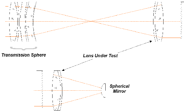
Figure 1 shows
two ways of analysing a lens with an interferometer. One test uses a
spherical reference mirror while the other uses a flat reference mirror
but requires an additional high quality focusing lens (or reference
sphere) in order to make the measurement. From the point of view of
diffraction the measurement using the reference sphere is preferred,
since the return mirror can be very close to the pupil of the lens under
test, therefore the pupil and its image via the mirror can both be very
close to focus on the interferometers camera faceplate. This is not
possible using the other arrangement, diffraction will be present
especially if the spherical mirror radius is small so that it is
physically far from the lens under test. Many tests in the infra-red use
high grade ball bearings as return mirror ö it is important that any
analysis of the interferograms takes into account the limitations of the
method.
 |
|
Figure
1. Reflection Configurations
|
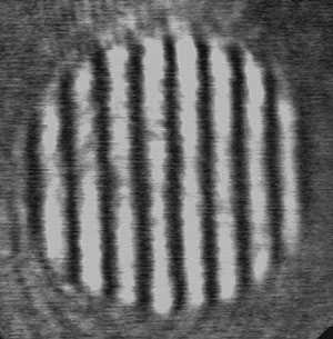
Figure 2 shows the effect of diffraction on the pupil imagery in
the interferometer.
|

|

|
| Focused
Pupil |
Unfocused
Pupil |
|
Figure
2. Pupil Imagery
|
In the unfocused
case, diffraction rings can clearly be seen inside the pupil. This has
the effect of breaking up the interference pattern such that the fringes
are discontinuous or vary in width due to contrast changes. Any
automatic fringe analysis program must be used with caution when
analysing such fringes. In general the peak to valley wavefront
aberration reported will be worse than the actual for the lens under
test.
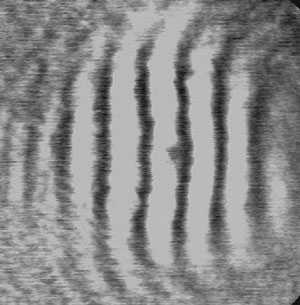
While figure 2 shows
the effect of diffraction within the optical pupil, the other common
case is when the diffracted radiation appears outside the pupil. This
has the effect of blurring the pupil edge so its size is uncertain and,
because the diffracted radiation has a different curvature to the main
beam, any interference fringes will curve within this zone. The effect
is very similar to that seen with Spherical Aberration especially that
of higher order and if not corrected can lead to a large departure in
measured vs. actual performance. This situation is shown schematically
in Figure 3.
|

|

|
|
Focused
Pupil
|
Unfocused
Pupil
|
|
Figure
3. Pupil Imagery Effects on Fringes
|
In this case, if information is known
about the size of the pupil within the interferogram, it is
possible to mask out much of the effects of diffraction simply by
ignoring those parts outside the pupil.
There will be cases
where it is impossible to achieve good pupil imagery without going to
great expense. In such circumstances, double pass interferometry can
still provide a confidence test on system performance, but ultimate
proof may require a single pass test, either by interferometry or by non
coherent broad band MTF testing or similar.
Infra-red
interferometry relies on sensing using an Infra-red camera, either
staring array CMT or a Pyroelectric vidicon tube. The latter is the most
used, mainly because of the cost of the camera. The cameras exhibit
random noise on the video signal. this is most obvious in the 3 to 5
micron waveband, where available, affordable lasers tend to be of low
power (typically 5-10mWatts). High signal gain is required to provide
sufficient contrast for recording fringe patterns or analysing fringe
patterns using either static or phase shifting software. Also of
relevance when laser power is marginal is the profile of the laser beam.
As much of the beam as possible must be used to maximise contrast but
this does mean that, due to the profile, the contrast varies across the
interferogram. This is particularly noticeable when using HeNe lasers at
3.39microns where perhaps only 5 to 10mWatts of power is available. This
can have the effect of making fringes appear both fainter and thinner
towards the edge of the pupil. When analysing with static fringe
analysis packages care needs to be taken to check that the digitised
fringes accurately represent the real shape of the fringe pattern.
The problems raised
by laser power profiles is greater when using Phase Shifting systems.
Phase shifting system involve a threshold contrast below which phase
will not be measured. This normally shows as a blank space in the
resulting phase map. This can be remedied by reducing the threshold.
However, using Pyroelectric vidicons with marginal laser power
represents a very noisy environment. Reducing the threshold too far mean
that the system can pick up on random noise in the picture and allocate
phase values which significantly larger than any other area of the
pupil. This has the effect of a gross distortion of the results. A
fine balance needs to be trodden between these two situations such that
phase information is available over the whole pupil without random noise
causing a problem. Generally with 3.39 micron systems, the threshold
needs to be set at around 2.5% to 3.5%.
At 10,6 microns,
these problems donāt occur. The main problem in the upper IR waveband
is finding ways of dumping excess energy ö normally with CaF2 filters
though with tuneable systems a wire grid polariser is necessary. This
means that the central part of the beam can be used ensuring a much
flatter profile, and sufficient power can be allowed through in order to
enable the pyroelectric vidicon camera to be set to low gain, thereby
reducing noise to an insignificant level. Further development in compact
high quality 3-5 micron lasers is eagerly anticipated.
|


